Leave Your Message

7 Wire Rope Clip Tips for Safe Cable Clamping

A Wire Rope Clip / Cable Clamp may look like a small piece of hardware, yet its setup can affect the security of a cable connection. A misplaced saddle, unevenly tightened nuts, or damaged wire strands can undermine an otherwise careful job. These details are easy to overlook. This guide shares seven practical tips for checking the clip, preparing the cable, and tightening the assembly with care.

Start by matching the clip to the wire rope’s diameter and following the manufacturer’s instructions for clip quantity, spacing, orientation, and torque. There is no safe universal shortcut; requirements can vary with the hardware and application. Keep the work area clean, inspect threads and cable for wear, and use a suitable wrench rather than guessing by feel. Small details matter. After tightening, check the connection again as directed by the manufacturer, especially if the cable will carry a load. A neat-looking assembly is not proof that it is secure. Even experienced hands can miss a detail, so a deliberate second check is worthwhile. These tips are general guidance, not a replacement for product specifications or qualified advice for critical lifting or life-safety uses.
7 Wire Rope Clip Tips for Safe Cable Clamping

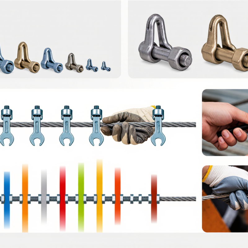
Select a Wire-Rope Clip Rated for the Rope Diameter and Construction

A wire-rope clip must match the rope’s actual diameter, not a nearby size that seems to fit. Measure the rope with calipers when possible; coatings, wear, and deformation can affect the reading. Then check the clip maker’s specifications for both diameter and rope construction. A clip intended for one rope type may not grip another reliably. This matters with compacted, rotation-resistant, or fiber-core ropes, whose build can differ from standard steel-core rope.

Fit is only part of the choice. Confirm that the clip is rated for the intended application, and follow its instructions for clip count, spacing, orientation, and tightening torque. On common U-bolt clips, the saddle sits on the live rope end and the U-bolt bears on the dead end. Check the instructions for the exact model. Small details matter. A mismatched clip can crush strands or slip under load, even when the assembly looks tidy. Clip terminations also reduce rope strength compared with an undisturbed rope, so do not treat a clip’s size rating as proof of the finished assembly’s capacity. Inspect the rope and hardware before installation, and recheck the nuts after the initial loading period if the maker requires it. Measuring twice is sensible. Guessing is not.

Set Clip Count and Spacing from the Manufacturer’s Diameter Table

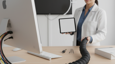
A wire-rope clip layout is not a guesswork detail. ASME B30.26-2020 covers wire-rope clips as rigging hardware, while manufacturers publish diameter-specific installation tables. Those tables may differ by clip design and rope construction. Check the exact rope diameter, required clip count, spacing, turnback length, and tightening torque. A chart for 1/2-inch rope is not a safe substitute for the chart covering your actual rope and clip.

Measure the rope before forming the eye; coatings and wear can make the diameter hard to judge. Lay out each clip at the table’s stated spacing, then check that the clips face the correct way and sit squarely. The Wire Rope Technical Board’s Wire Rope Users Manual also stresses following the clip maker’s installation guidance. Small mismatch, big consequence. Recheck the table after tightening, because clips can shift as the rope seats.

Tip: Keep the diameter table beside the work area. Mark each clip position with chalk, and use a torque wrench when the instructions specify torque. Don’t borrow a clip count from a nearby rope size. It feels slower. It is safer.

Wire Rope Clip Count and Spacing by Rope Diameter

Example reference values for selected rope diameters. Follow the clip manufacturer’s table for the exact clip type and rope construction; do not use this chart as a substitute for that table.

Clip spacing is shown in inches. Space clips evenly along the rope end as directed by the applicable manufacturer’s instructions, and install each clip with the saddle on the live end.

Orient Each U-Bolt with the Saddle on the Live Rope End

For a wire-rope eye, orient each U-bolt so it bears on the dead end; the saddle must sit on the live, load-bearing rope. OSHA’s 29 CFR 1910.184(e)(5) specifies this arrangement for U-bolt clips used to form sling eyes. In practical terms, the rope’s short tail goes beneath the U-bolt, while the continuous rope rests in the saddle.

Check every clip before loading. A reversed clip can crush the live rope and weaken the connection.

Use the clip maker’s instructions for the required number, spacing, and tightening torque; rope diameter alone is not a safe shortcut. Keep the clips aligned, then tighten the nuts evenly with a calibrated torque wrench. Recheck after the initial load, since the wire can settle.

Small detail. Big consequence.

The U.S. Bureau of Labor Statistics counted 5,283 fatal work injuries in 2023, across all industries; its report does not identify wire-rope clip failures separately. That figure signals the wider stakes, not a clip-specific risk estimate. OSHA’s rule and the manufacturer’s instructions are more useful for this fitting.

It is easy to glance at the hardware and assume the saddle faces correctly. Pause, trace the live rope with a finger, and verify before lifting. I would not rely on memory alone.

Tighten to the Manufacturer’s Torque Data and Recheck After Loading

Torque is not a setting to guess by feel. Use the torque value for the exact clip size and rope construction in its manufacturer’s instructions; different hardware can require different values. Keep the threads clean, seat the live rope in the saddle, and place the U-bolt over the dead end. Small details matter.

OSHA’s construction standard, 29 CFR 1926.251(c)(5), says clip spacing should be at least six rope diameters and requires nuts to be retightened after a newly installed wire rope has operated for one hour. Treat that as a useful checkpoint, not a substitute for the product’s instructions. After loading, unload and inspect the termination: look for shifted clips, a gap at the saddle, or nuts that have backed off. Recheck torque with a suitable calibrated wrench, following the manufacturer’s procedure. Never tighten a loaded connection. A paint mark across each nut and clip can reveal movement during inspection. It is a simple aid, not proof of correct torque. I would not assume one successful lift settles the matter; the rope can seat and the clamping force can change.

7 Wire Rope Clip Tips for Safe Cable Clamping - Tighten to the Manufacturer’s Torque Data and Recheck After Loading

No. Safety Tip What to Do Why It Matters
1 Match the clip to the rope Use clips specified for the wire rope’s diameter, construction, and application. Check the clip instructions for compatibility and any limits on use. A clip that is the wrong size or type may not grip the rope correctly and can reduce the security of the termination.
2 Orient the clip correctly For a common U-bolt clip, place the U-bolt over the short, unloaded tail (dead end) and the saddle on the standing, load-bearing part (live end). Follow the clip maker’s instructions if the design differs. Incorrect orientation can damage or crush the live rope and compromise the connection.
3 Use the specified number and spacing Install the number of clips and the spacing stated for the exact clip and rope size. Keep the clips aligned and evenly spaced along the prepared termination. Clip count and spacing are design-dependent; a universal layout should not be assumed.
4 Tighten to the specified torque Use the manufacturer’s torque data for the exact clip size and design. Tighten the nuts evenly with a suitable calibrated torque wrench, following the stated installation sequence. Under-tightening can allow slippage; over-tightening can damage components or the wire rope. There is no single torque value suitable for every clip.
5 Inspect the assembled termination Before loading, check that the rope is seated correctly, the clips are positioned as instructed, and the nuts and threads show no visible damage. Confirm that the tail length meets the installation instructions. A visual check can identify assembly errors or damaged parts before the connection is put into service.
6 Recheck after initial loading After the connection has been loaded, safely unload and secure the assembly before inspection or adjustment. Recheck the nuts and retighten only as directed by the manufacturer; do not work beneath a suspended load. Initial loading can seat the rope and affect the connection. Safe access and the specified recheck procedure help prevent injury and avoid improper adjustment.
7 Inspect regularly and replace damaged parts Set inspection intervals according to the application and applicable safety requirements. Look for rope slippage, broken wires, corrosion, deformation, loose nuts, or other damage; remove defective components from service. Wear, corrosion, vibration, and changing service conditions can affect the connection over time. A damaged clip or rope should not be relied on.

Inspect the Finished Termination Using Applicable ASME B30.26 Guidance

Inspect the finished termination as a load-bearing assembly, not merely a row of tightened nuts. Under ASME B30.26-2020, rigging hardware should receive frequent inspection before use and periodic inspection at intervals not exceeding 12 months; service severity may require shorter intervals. Check the clip bodies for cracks, distortion, heavy corrosion, or worn threads. Confirm each U-bolt and saddle is correctly positioned for the rope end, with spacing and torque matching the clip manufacturer’s instructions. ASME provides the inspection framework; it does not replace product-specific installation requirements.

Look closely for crushed strands, broken wires, or a shifted rope tail. A paint mark across the nut and threaded leg can help reveal movement after handling or loading. Keep the termination unloaded during inspection, and compare it with a clear installation record when available. If the clip arrangement is uncertain, stop and have a qualified person assess it.

Small details matter. A clip can look tidy while hiding damage beneath its saddle, and a visual check cannot prove its rated capacity. Record defects and remove questionable hardware from service in line with site procedures and applicable ASME guidance.