Leave Your Message

7 Tips for Choosing a Bus Drop Cable Support Grip?

Choosing a Bus Drop Cable Support Grip is not a cosmetic decision. It affects cable stability, strain control, maintenance access, and long-term installation reliability. A grip that looks strong in a catalog may still perform poorly when exposed to vibration, heat, moisture, or repeated movement.

Mike Holt, a respected electrical training expert, offers a practical reminder: “The installation is only as safe as its weakest connection.” That principle matters here. The correct grip must match the cable diameter, construction, weight, routing direction, and environmental conditions. It should also support the cable without crushing its jacket or transferring excessive force to terminals and connectors.

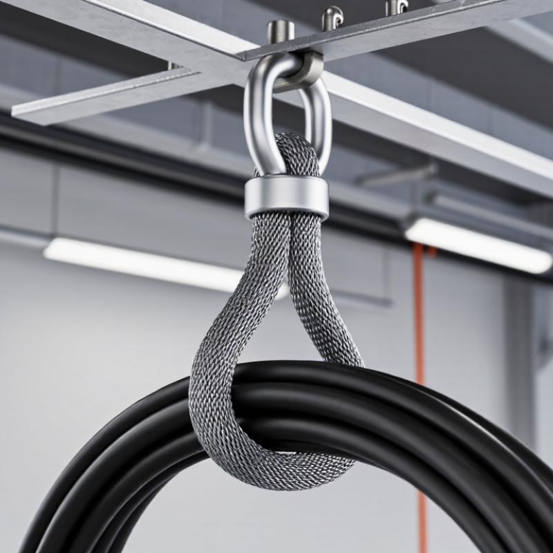
This guide presents seven practical tips for selecting a Bus Drop Cable Support Grip. It considers mesh design, load capacity, eye configuration, material compatibility, and installation space. Small details matter. A sharp edge near the cable can create damage over time. An undersized grip may slip during maintenance. An oversized grip may fail to hold the cable firmly.

Real installations are rarely perfect. Access may be limited. Cable paths may be crowded. Measurements can also be rushed. That is where careful checking becomes valuable. Confirm the cable dimensions, inspect the support point, and review the manufacturer’s load information before ordering. A little hesitation is better than a costly correction.

The goal is not simply to choose the strongest product. It is to choose a dependable support grip that fits the complete installation and remains secure throughout its service life.
7 Tips for Choosing a Bus Drop Cable Support Grip?

Identify the Cable’s Diameter, Weight, Voltage, and Minimum Bend Radius

7 Tips for Choosing a Bus Drop Cable Support Grip

Measure the cable’s actual outside diameter, not the nominal trade size. Jacket thickness can change the result. A grip that feels slightly loose may slip under vibration, while an undersized grip can damage the jacket. Check the manufacturer’s diameter range and measure several points along the cable.

Calculate the cable weight per meter, then include connectors, fittings, and any hanging length. The grip’s working load should exceed this total with a sensible safety margin. Do not rely on appearance.

I once underestimated a short drop because the cable felt light by hand. That judgment was wrong.

Confirm the cable’s voltage rating and installation environment, including heat, moisture, and movement. The grip materials must suit these conditions. Verify compatibility with the cable jacket, especially when oils or cleaning chemicals are present. Respect the cable’s minimum bend radius during installation. Measure the radius from the cable’s centerline, not from its outer edge. A tight bend near the grip can create hidden conductor stress. Keep the grip aligned with the cable path, and avoid twisting it during tightening. Check support spacing and the manufacturer’s installation instructions. Inspect the assembly after energizing, then recheck it after vibration or temperature changes. Field conditions are rarely perfect. Re-measure when the cable route changes.
Match Grip Size to Cable OD and Verify the Manufacturer’s Load Rating

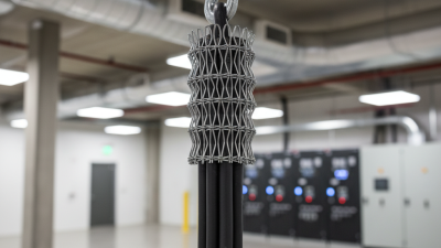
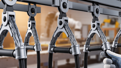
Choosing a bus drop cable support grip starts with the cable’s actual outside diameter, not its printed trade size. Measure the jacket with a calibrated caliper after installation conditions are understood. Temperature, armor, and protective coverings can change the effective diameter. A grip that is too loose may slide, while an undersized grip can damage the jacket.

Check the manufacturer’s stated diameter range and match the grip carefully. Do not rely on appearance. Seven practical checks include cable OD, grip style, eye position, installation space, environmental exposure, termination method, and rated load. The load rating must support the cable’s weight, movement, and expected service forces. Confirm whether the rating is working load or ultimate breaking strength. These values are not interchangeable.

Ask for the technical data sheet and any applicable test information. Inspect the mesh for damaged wires before use. Keep the support point aligned with the cable path, avoiding sharp bends near the grip. In field inspections, installers sometimes measure only the cable jacket and forget added conduit or tape. That mistake is easy to make. Recheck the finished assembly, then compare the total suspended load with the manufacturer’s rating and required safety margin. If the dimensions or rating seem unclear, pause the installation and request written clarification.

7 Tips for Choosing a Bus Drop Cable Support Grip? - Match Grip Size to Cable OD and Verify the Manufacturer’s Load Rating

Tip Selection Focus What to Check Practical Data or Method Acceptance Guidance
1 Measure the actual cable outside diameter Use the finished cable diameter, including the jacket, rather than the conductor size or nominal trade size. Record the measured cable OD in millimetres or inches. Example: 25.4 mm (1.00 in), 31.8 mm (1.25 in), or 38.1 mm (1.50 in). Take measurements at several points if the jacket is irregular. Use the largest credible OD when comparing with the grip manufacturer’s published range.
2 Match the grip size to the cable OD range Confirm that the cable OD falls within the grip’s published minimum and maximum diameter range. Example selection check:
Cable OD: 31.8 mm (1.25 in)
Grip range: 25–38 mm (0.98–1.50 in)
Result: within range
Do not force a cable into a grip that is undersized, and do not rely on a grip that only barely covers the stated range without checking the installation instructions.
3 Verify the manufacturer’s working load rating Check the published working load limit for the exact grip type, size, eye configuration, and installation orientation. Estimate the supported load as:
Required load = cable weight per metre × supported length + accessory weight.
Example: 3.0 kg/m × 8 m + 2 kg = 26 kg before any project-specific design factor.
The published working load rating must exceed the calculated service load and any additional design or safety factor required by the project specification and applicable regulations.
4 Select the correct grip construction Choose between materials and configurations suitable for the cable jacket, movement, temperature, moisture, and electrical environment. Typical considerations include galvanized or stainless steel mesh, single-eye or double-eye designs, closed or split mesh, and strain-relief or support applications. Use corrosion-resistant construction in wet, chemical, outdoor, or washdown areas. Confirm material compatibility with the cable jacket and surrounding equipment.
5 Check the cable bend radius and routing path A support grip carries axial load but does not eliminate the cable manufacturer’s minimum bend-radius requirement. Use the cable datasheet value. Example: if the required minimum bend radius is 8 × cable OD and the cable OD is 31.8 mm, the minimum radius is approximately 254 mm. Provide adequate clearance at the grip, enclosure entry, and transition points. Avoid sharp bends, twisting, flattening, and side loading of the grip.
6 Confirm termination and hardware compatibility Verify that the eye, shackle, hook, or mounting point can accept the grip and sustain the applied load without interference. Check eye opening, mounting-hole diameter, hardware diameter, available clearance, and the allowable load direction. The support point should align with the intended line of pull. Do not use hardware that reduces the eye opening, creates a sharp contact edge, or introduces bending and prying forces not covered by the grip rating.
7 Inspect installation and plan periodic checks Correct installation is essential because uneven loading, damaged mesh, or cable movement can reduce support performance. Inspect for broken wires, corrosion, pulled mesh, jacket damage, loose hardware, excessive sag, and signs of rubbing. Recheck after initial energization or equipment movement. Replace the grip if the mesh, eye, attachment hardware, or cable jacket shows damage. Follow the manufacturer’s installation, inspection, and replacement instructions.
Important: Cable outside diameter, cable weight, minimum bend radius, grip working load, installation orientation, and environmental limits must be confirmed from the current cable and grip manufacturer documentation before installation. The example values above are engineering selection examples, not universal product ratings.

Choose Materials for 600 V Service, Temperature, and Corrosion Exposure

7 Tips for Choosing a Bus Drop Cable Support Grip

For 600 V service, verify the grip’s rated voltage before comparing price or appearance. Select a support grip designed for the cable’s actual diameter, weight, and bend radius. A loose mesh can shift during vibration, while an undersized grip may damage the jacket. NFPA 70, 2023 Edition, emphasizes listed equipment and secure wiring methods for these installations. Follow the cable manufacturer’s pulling and support limits, not guesswork.

Material selection depends on the surroundings. Stainless steel performs well where moisture, washdown, or salt exposure can accelerate corrosion. Galvanized steel may suit cleaner indoor areas, but coating damage deserves attention. Choose an insulating or polymeric protective finish when the grip could contact dissimilar metals. Check the operating temperature range, including heat from nearby equipment and cold during shutdowns. IEC 60502-1 identifies conductor and insulation temperature limits that should guide this review.

Inspect the support point, hardware, and strain path together. Keep the grip clear of sharp edges, standing water, and repeated flexing. ESFI’s analysis of U.S. Bureau of Labor Statistics data recorded 126 electrical fatalities in 2020, showing why small installation decisions matter. Do not rely only on a catalog photograph. Ask for test documentation, corrosion information, and load data. A common mistake is choosing by diameter alone. Field conditions often change the answer. Recheck the selection after installation.

Check NEC 400.10, UL Listings, and Required Support Spacing

Choosing a bus drop cable support grip starts with NEC 400.10.

This section addresses securement, strain relief, and protection from pulling forces. Do not treat the grip as decoration. It must prevent cable weight from stressing terminals, splices, or enclosure entries.

Check the cable’s listing before selecting a grip. The listing should match the cable construction, diameter range, temperature rating, and installation environment. Review the manufacturer’s instructions, certification markings, and tested use conditions. A grip approved for general flexible cable may not suit a bus drop assembly. That mistake is easy to make.

Support spacing deserves equal attention. NEC 400.10 may not provide every spacing value for your specific installation. The cable listing, installation instructions, project specifications, and other applicable NEC requirements may control. Measure the actual cable diameter, then confirm the grip’s sizing range. Tightening by appearance is unreliable.

I have seen supports installed too far apart, leaving a visible cable sag near the connection. It looked acceptable from the floor, but the termination carried unnecessary tension. Inspectors and qualified electricians should verify spacing, grip orientation, load capacity, and strain relief before energizing the equipment. Local authority requirements can also differ, so confirm the current adopted code edition. Leave room for correction. One overlooked detail can weaken an otherwise careful installation.

Install the Grip Correctly and Inspect It at Least Annually

Choosing a bus drop cable support grip starts with the cable, not the grip. Match the grip to the cable’s outside diameter, weight, construction, and installation environment. Check the rated working load, eye orientation, and required bend radius. A grip that feels tight may still be unsuitable.

Install the grip correctly and inspect it at least annually. Clean the cable before fitting it, then position the grip over a firm, undamaged section. Secure the eye to the approved support point, and keep the cable free from sharp bends, twisting, and contact with hot surfaces. Do not let the grip carry more load than its rating. Verify hardware torque against the installation instructions. Small details matter.

During each inspection, look for broken strands, flattened mesh, corrosion, loosened fittings, cable jacket damage, and unusual sag. Photograph defects and record the inspection date, load conditions, and corrective action. The U.S. Bureau of Labor Statistics recorded 145 fatal occupational electrical injuries in 2022, showing why support hardware deserves serious attention. NFPA 70B promotes documented, risk-based electrical maintenance rather than a one-time check. Annual inspection is a sensible baseline, but vibration, moisture, movement, or heavy loading may require shorter intervals. I would not treat a clean appearance as proof of safety. Hidden strand fatigue can develop quietly. Good records help reveal that pattern.