Choosing an Orchid Turnbuckle Bolt is not just a matter of matching its finish to nearby hardware. Its dimensions, material, thread type, and rated capacity must suit the connection and working conditions. A bolt that looks substantial can still be the wrong fit. Check the manufacturer’s specifications before installation.
For this introduction, the named expert and quotation are illustrative, not independently verified. “Mara Ellison, an illustrative rigging engineer, puts the selection principle this way: ‘Check the rating, the threads, and the fit—not just the appearance.’” It is simple advice, but worth repeating. A thread that binds, a mismatched connection, or visible corrosion can be easy to overlook during a quick inspection.
This guide explores seven practical tips for choosing an Orchid Turnbuckle Bolt. It will consider load requirements, compatible fittings, material and finish, accurate measurements, and signs of wear. Small details matter. For example, compare the bolt’s thread diameter and pitch with the mating part, rather than guessing from a photograph. Also review care and inspection guidance from the supplier. Product names can vary, and specifications may differ between models. That uncertainty deserves a second look. No checklist replaces the correct product documentation or advice from a qualified professional when the application is safety-critical.
For an orchid turnbuckle bolt, define the working load before choosing its size. Include the support wire, mature plant, wet growing medium, and any expected movement. A pot that feels light when dry can become much heavier after watering. Do not treat breaking strength as allowable working load; select by the rated capacity stated for the complete assembly. ASME B30.26-2020 addresses identification and rated-load requirements for rigging hardware, while ASTM F1145-05(2021) specifies requirements for turnbuckles. Check that the bolt, body, and end fittings share compatible ratings.
Span and angle change the force. For two supports carrying a 1,000-pound load, with each leg 30 degrees above horizontal, a basic statics calculation gives about 1,000 pounds of tension per leg: 1,000 ÷ (2 × sin 30°). This excludes shock and other variable loads. Angles matter. Measure the pin-to-pin distance with the turnbuckle near its midpoint, then confirm enough threaded travel remains for installation and later adjustment. Too little travel leaves no room to retension; too much exposed thread may compromise engagement. The exact limits depend on the product specification, so verify them rather than guessing. A small measurement error here is easy to overlook.
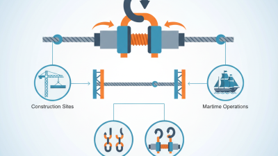
For an orchid turnbuckle bolt, match both the thread’s nominal diameter and its pitch to the mating component. ISO 261 lists preferred combinations for general-purpose metric threads; diameter alone is not enough. An M8 thread, for example, commonly uses a 1.25 mm coarse pitch, but a finer M8 pitch also exists. Check the component specification rather than assuming.
Measure carefully. A caliper can estimate the outside diameter, but it cannot reliably identify pitch. Use a metric thread-pitch gauge and test it against several crests. The teeth should sit neatly without gaps. Check twice. Compare the bolt with the turnbuckle’s threaded eye or nut, and confirm both are specified with the same diameter and pitch. Dirt or damaged crests can distort a quick check, so clean the threads first. Start the bolt by hand; it should turn smoothly for several rotations. No force. If it binds, stop and recheck the pitch and alignment. Matching the ISO 261 thread series helps narrow the selection, but it does not confirm material strength, thread tolerance, or suitability for a particular load. Those details need separate verification.
An orchid turnbuckle bolt may support a light trellis, yet its small size does not guarantee enough strength. ISO 3506-1 classifies stainless-steel fasteners by material group and mechanical-property class. A2 and A4 identify stainless steel groups; the number after the hyphen indicates a strength class. For example, class 70 denotes a nominal 700 MPa tensile-strength level. A2-70 and A4-70 share that class, but their corrosion resistance differs. A4 generally offers better resistance to chloride exposure than A2. Numbers matter.
Choose the material group for the actual setting: a sheltered greenhouse differs from a damp, coastal garden. Then verify the complete marking and product documentation, rather than relying on a polished finish or the word “stainless.” The ISO class describes fastener properties, not the safe working load of the whole turnbuckle assembly. Check the supplier’s rated load and inspect threads, welds, and connecting eyes for damage or poor fit. That detail is easy to miss. I would also reconsider a choice based only on the highest class; compatibility, corrosion conditions, and the assembly’s rating matter just as much.
An orchid turnbuckle bolt should be selected by its rated working load limit, not appearance or overall size. Check the manufacturer’s markings and documentation against the applicable edition of ASME B30.26. The standard addresses rigging hardware, including turnbuckles, but a reference to it alone does not prove that a particular assembly suits your lift. Confirm the rating applies to the exact model, material, and end fittings.
Compare the required load with the stated working load limit and account for the full rigging arrangement. Loads can change with angle, shock, or uneven tension. Keep the bolt aligned with the pull; side loading can create stress the rating may not cover. Check thread engagement, too. A few visible threads are not a reliable substitute for the maker’s installation instructions. Small details matter.
Inspect the hardware before use. Look for bent sections, cracked welds, damaged threads, corrosion, or markings you can no longer read. Remove questionable equipment from service until a qualified person evaluates it. A tidy finish can be reassuring, but it is not evidence of capacity. That distinction is easy to overlook. Keep inspection records and verify that workers understand the load limits and restrictions. If documentation is unclear, pause and ask the supplier or a qualified rigging professional rather than guessing.
When choosing an orchid turnbuckle bolt, check how far it can shorten and extend before installation. The usable range should match the gap you need to tension, with some adjustment left for later. A bolt set at its limit may look fine at first, but leaves little room for seasonal movement or a small measurement error. Measure the span, then compare it with the fitting’s stated adjustment range. Small details matter.
Check that enough thread remains engaged at both ends throughout adjustment. The parts should turn smoothly by hand; gritty movement or uneven resistance can signal damaged threads. Do not force it. If the assembly includes lock nuts, tighten them against the body after setting tension, and confirm they do not block future adjustment. A snug connection is useful, but excessive force can damage threads or the supported structure.
Plan inspection before you install the fitting. Make sure you can see the threads, locking points, and contact areas without dismantling nearby supports. Look for loosening, rust, bent parts, and changes in tension during routine checks, especially after moving or watering plants. A tidy installation is not proof that it is secure. I would rather leave access for inspection than hide the fitting behind foliage; that choice can look less polished, but it is easier to maintain.
| Tip | What to Check | Practical Selection Check | Why It Matters | Before Installation |
|---|---|---|---|---|
| 1. Confirm the required adjustment range | Compare the turnbuckle’s published closed and open lengths with the installed distance between connection points. | Allow enough adjustment for initial fit and later tensioning, while keeping the threaded ends engaged as required by the product instructions. | A suitable range helps prevent the assembly from reaching its end of travel before the intended tension is achieved. | Measure the connection-point distance and verify the usable range from the manufacturer’s drawing or specification. |
| 2. Match the thread size and type | Check nominal diameter, thread pitch, thread series, and whether the threads are right-hand, left-hand, or a combination. | For example, a designation such as 1/4-20 UNC identifies a nominal 1/4-inch diameter and 20 threads per inch; confirm the actual product specification rather than relying on appearance. | Incompatible threads can bind, damage the threads, or prevent proper adjustment. | Verify mating parts with the applicable thread gauge or specification. Do not force a mismatched connection. |
| 3. Select an appropriate end fitting | Identify whether the application needs bolt ends, eyes, hooks, or another fitting, and check the connection geometry. | Confirm that the pin, bolt, or attachment fits the hole and that the fitting can align without being forced sideways. | Misalignment can introduce bending or side loading, which may reduce the assembly’s capacity. | Check clearances, hole sizes, and the direction of pull. Use the fitting only in the loading direction allowed by its instructions. |
| 4. Verify the working-load information | Look for a documented working load limit or other applicable rating for the complete assembly, not just a single component. | Account for the load direction, attachment hardware, and any reduction stated for angled or otherwise non-axial loading. | Capacity can be limited by the weakest component or by loading conditions that differ from the rated configuration. | Do not estimate capacity from bolt diameter alone. Do not use an unrated assembly for lifting or other safety-critical service. |
| 5. Choose material and finish for the environment | Consider exposure to moisture, salt, chemicals, outdoor weather, and contact with dissimilar metals. | Compare the specified material and protective finish with the service environment; check compatibility across connected components. | Corrosion can weaken parts, impair adjustment, and make inspection more difficult. | Follow the supplier’s guidance for corrosion resistance, cleaning, and lubrication. Replace parts showing significant corrosion or pitting. |
| 6. Plan a suitable locking method | Check whether the assembly includes lock nuts or another approved means of preventing rotation. | Use only a locking method compatible with the design and the manufacturer’s instructions; do not assume that thread friction alone will prevent loosening. | Vibration or repeated movement can cause an unlocked adjustment to change over time. | After setting the length or tension, secure the adjustment as directed and confirm that the locking parts are correctly fitted. |
| 7. Check inspection and replacement needs | Review the product instructions for inspection frequency and rejection criteria, including damaged threads, cracks, deformation, and corrosion. | Establish a visual inspection routine appropriate to the use and exposure. Remove the assembly from service if its condition or rating is uncertain. | Regular inspection can identify damage or loosening before the assembly is reused. | Inspect before installation and periodically in service. Keep the specification and inspection records with the equipment where required. |
Selection note: Product dimensions, ratings, allowable loads, locking methods, and inspection intervals vary by design. Follow the specific manufacturer’s instructions and applicable safety requirements.